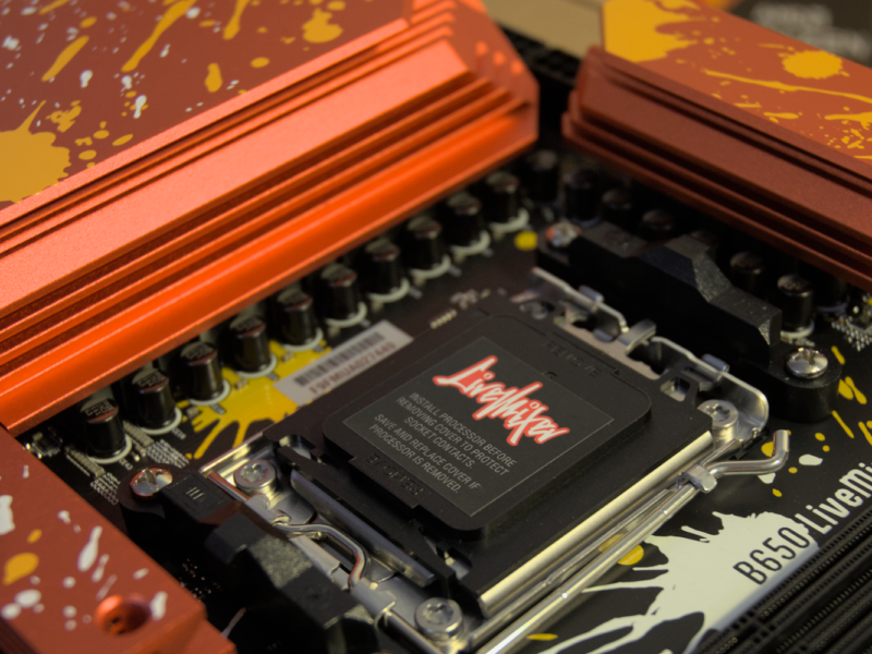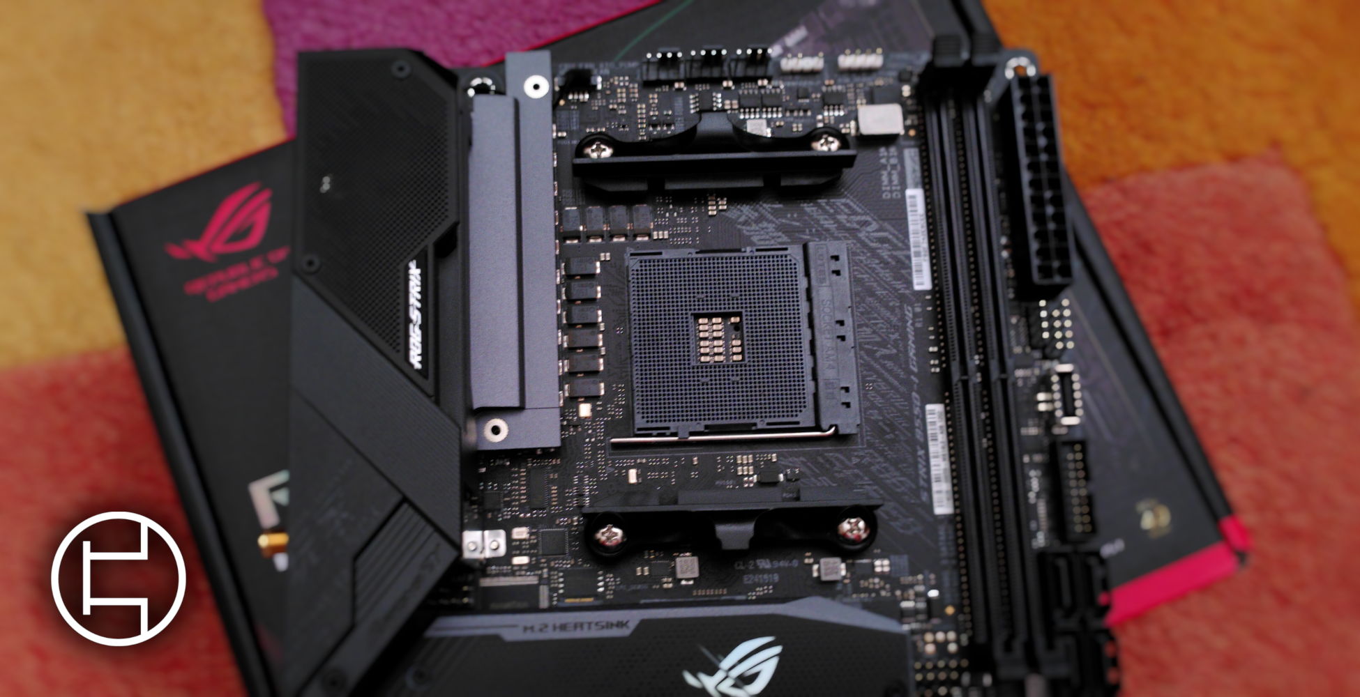
Introduction
The Voltage Regulator Module (VRM) on a motherboard converts and regulates the voltage for various Integrated Circuits on the Motherboard. It converts the 12/5/3.3 V DC coming from the Power Supply Unit into a much lower voltage needed for the ICs to function. This article is intended to give a quick insight into all the Components that are involved and then give its reader a basic understanding of how VRMs function.
Powerstages
An integrated power stage is the combination of a driver and its mosfets onto a single integrated circuit. It is also often called “DrMOS” due to this.
The designation “smart” power stage indicates that there are additional features added to the circuit such as digital current monitoring.
Chokes – Inductor
Inductance is the ability of storing electrical energy in a magnetic field. Just as any magnetic you know also a magnetic field is forceful against changes, so once the current changes it will create force to prevent it from doing so. This allows to lower or even discontinue the current for a short time while seeing no difference in current.
An Inductor is a passively working electronic component which stores electrical energy in form of magnetic energy. It uses a Conductor that is wound into a coil to generate the magnetic field mentioned above. The Inductor creates a magnetic field in the clockwise direction when electricity flows into the coil from left to right. The more turns around with which the conductor is wound around the core, the stronger the magnetic field gets.
So by adding a resistor to the circuit its able to change to voltage instead of its current.
Controller
The controllers of the VRM come in the shape of PWM – short for Pulse width modulation – controllers. As the name suggests, they control the duration of the pulse that is sent to the driver ICs which control the MOSFETs opening and closing. This duration is given as the duty cycle, which describes the amount of time within a cycle where the ICs are active. In the context of a VRM, a 50% duty cycle would mean that the voltage is rising for 50% of the time, and falling for the other 50.
Controllers commonly have multiple channels, that is multiple PWM lines, which are independent of each other. This is the amount of Power Phases a controller can control without the use of doublers. How quickly the different phases take over in voltage regulation is determined by the switching frequency. The controllers can include additional features such as monitoring or protections.
Phases
A phase is composed in its most basic form of two MOSFETs, an inductor, a driver and a few capacitors. They are one “workunit” within a VRM. How they exactly work will be explained later in this article.
Doublers
A Doubler is an electrical component that doubles the frequency of an input signal. It takes 1 PWM Signal (frequency) and splits it cycle into two that. It does that by switching the PWM Signal to 2 separate circuits so it remains in a constant harmony. In a VRM its used to create 2 separated Phases that relief each other while making sure they are running at the Frequency defined by the PWM Controller. For example it splits a frequency of 300khz to 150 khz per outlet in a rotary curve.
Component Doubling
Component Doubling is a method that unlike the implementation of a Doubler just splits the PWM Signal to two phases. So instead of causing two switching circuits it splits the PWM Signal in half between two phases that now run at a parallel frequency. This brings relief to each Phase but isn’t as effective as a two-phased circuit using a doubler. It can also be tripled or quadrupled but the common integration is a doubling.
Voltage Rails
As a the many parts on the Motherboard require different voltages, there are many voltage rails. The most notable are vCore, which is the Voltage the CPU cores receive, vSOC, which is what the SOC, or uncore. of a CPU receives and vMEM, which is the Memory power for the RAM.
Heatsink
As electrical components heat up, they naturally need a way to dissipate this heat. Heatsinks increase the surface area that is able to dissipate heat and therefore keep these components cool.
Transient Response
Transient Response in the context of a VRM is how quickly said VRM can react to changes of demand in voltage. Load Line calibration is often used to combat the effects of bad transient response, but these concepts will be discussed in a further article.
Operation
The typical implementation of a VRM is via a switching regulator, most commonly a buck converter. The most basic implementation is a single phase.
In its most simple form, it consists of a dc power source, in this case the PSU, two MOSFETs, acting as switches, the load, be that a Processor, Memory or otherwise, and an Inductor/Choke.
Basic Principle – Single Phase
When the high-side MOSFET is closed, current is allowed to flow across, making the voltage at point A 12V. It then flows into the Inductor which stores the energy into a magnetic field. While this happens, the inductor will resist the electrical current flowing through it and create a voltage drop at the output at point B. As the field builds up, the resistance gets lower and lower until it reaches 12V. How quickly this happens is dependent on the inductance of the inductor. Below is a graph where you can see the Voltages at point A and B over time, with Inductors of different inductance.
When the high-side MOSFET is opened, the voltage at point A drops to 0V, however, the inductor still retains its magnetic field, which now rapidly collapses as there is no longer a current sustaining it. As the Circuit is no longer closed, all the energy stored in the inductor would go into the load, potentially damaging it. This energy would manifest as a huge voltage spike at point B. As MOSFETs react rather slowly, a diode is added in parallel to the low-side MOSFET, sustaining a closed circuit. The reason there is a MOSFET is due to the inefficiency of the diode. The voltage only flows through the diode in the time it takes from the high-side MOSFET being opened and the low-side MOSFET being closed, now the voltage would slowly drop back to 0V.
However, the reason for the VRMs existence is to provide a certain constant voltage to the IC to keep it operating.
The way in which this voltage is regulated is simply an application of the above. The high-side MOSFET is closed until the IC gets its desired voltage, then it is opened and the low-side closed. Before the voltage drops below an acceptable amount, the high-side is closed again and the cycle repeats itself.
Expanded – Multi Phase
Now that the basic principle is understood, let us expand the VRM. As one already knows, the voltage isn’t perfectly at its desired point the entire time, and one way to mitigate this is to add more phases. Other benefits include the load is dispersed across multiple circuits, increasing efficiency and making the generated heat easier to disperse while decreasing ripple.
For the sake of simplicity, we’ll add only a second phase. The principle stays the same no matter the number and the benefits scale.
The way in which multiple phases are utilized is by offsetting the time at which they are activated. By doing that, there will always be one phase charging its field up while the others are discharging. This makes the average voltage much more stable.
Further Reading:
Multiphase Buck design from start to finish – Texas Instruments